Product Description
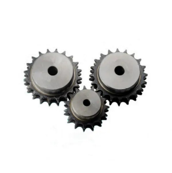
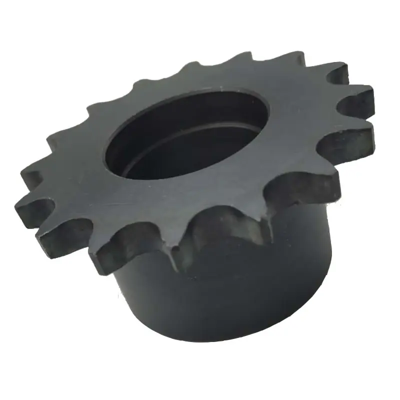
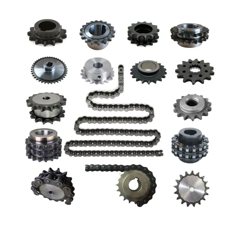
Stainless Steel Plastic Roller Chain Gear Platewheel Engineer Class Agricultural Pintle Cast Iron Weld On Hub Finished Bore Idler Bushing Taper Lock Qd Sprocket
Product Description
|
European standard sprockets |
|
|
DIN stock bore sprockets & plateheels |
03B-1 04B-1 05B-1-2 06B-1-2-3 081B-1 083B-1/084B-1 085B-1 086B-1 08B-1-2-3 10B-1-2-3 12B-1-2-3 16B-1-2-3 20B-1-2-3 24B-1-2-3 |
|
03A-1 04A-1 05A-1-2 06A-1-2-3 081A-1 083A-1/084A-1 085A-1 086A-1 08A-1-2-3 10A-1-2-3 12A-1-2-3 16A-1-2-3 20A-1-2-3 24A-1-2-3 |
|
|
DIN finished bore sprockets |
06B-1 08B-1 10B-1 12B-1 16B-1 20B-1 |
|
stainless steel sprockets |
06B-1 08B-1 10B-1 12B-1 16B-1 |
|
taper bore sprockets |
3/8″×7/32″ 1/2″×5/16″ 5/8″×3/8″ 3/4″×7/16″ 1″×17.02mm 1 1/4″×3/4″ |
|
cast iron sprockets |
06B-1-2-3 081B-1 083B-1/084B-1 085B-1 086B-1 08B-1-2-3 10B-1-2-3 12B-1-2-3 16B-1-2-3 20B-1-2-3 24B-1-2-3 |
|
platewheels for conveyor chain |
20×16mm 30×17.02mm P50 P75 P100 |
|
table top wheels |
P38.1 |
|
idler sprockets with ball bearing |
8×1/8″ 3/8″×7/32″ 1/2″×1/8″ 1/2″×3/16″ 1/2″×5/16″ 5/8″×3/8″ 5/8″×3/8″ 5/8″×3/8″ 3/4″×7/16″ 3/4″×7/16″ 1″×17.02mm 1 1/4″×3/4″ |
|
double simplex sprockets |
06B-1 08B-1 10B-1 12B-1 16B-1 |
|
American standard sprockets |
|
|
ASA stock bore sprockets |
-2 35-3 -2 40-3 50 50-2-50-3 60 60-2 60-3 80-80-2 80-3 100 100-2 100-3 120 120-2 120-3 140 140-2 160 160-2 180 200 |
|
finished bore sprockets |
|
|
stainless steel sprockets |
60 |
|
double single sprockets&single type Csprockets |
|
|
taper bore sprockets |
35 35-2 -2 50 50-2 60 60-2 80 80-2 |
|
double pitch sprockets |
2040/2042 2050/2052 2060/2062 2080/2082 |
|
sprockets with split taper bushings |
40-2 40-3 50 50-2 50-3 60 60-2 60-3 80 80-2 80-3 100 100-2 120 120-2 |
|
sprockets with QD bushings |
35 35-1 35-2 -2 40-3 50 50-2 50-3 60 60-2 60-3 80 80-2 80-3 100 100-2 100-3 |
|
Japan standard sprockets |
|
|
JIS stock sprockets |
140 160 |
|
finished bore sprockets |
FB25B FB35B FB40B FB50B FB60B FB80B FB100B FB120B |
|
double single sprockets |
40SD 50SD 60SD 80SD 100SD |
|
double pitch sprockets |
|
|
speed-ratio sprockets |
C3B9N C3B10N C4B10N C4B11 C4B12 C5B10N C5B11 C5B12N C6B10N C6B11 C6B12 |
|
idler sprockets |
35BB20H 40BB17H 40BB18H 50BB15H 50BB17H 60BB13H 60BB15H 80BB12H |
|
table top sprockets |
P38.1 |
|
Material available |
Low carbon steel, C45, 20CrMnTi, 42CrMo, 40Cr, stainless steel. Can be adapted regarding customer requirements. |
|
Surface treatment |
Blacking, galvanization, chroming, electrophoresis, color painting, … |
|
Heat treatment |
High frequency quenching heat treatment, hardened teeth, carbonizing, nitride, … |
Customization process
1.Provide documentation:CAD, DWG, DXF, PDF,3D model ,STEP, IGS, PRT
2.Quote:We will give you the best price within 24 hours
3.Place an order:Confirm the cooperation details and CZPT the contract, and provide the labeling service
4.Processing and customization:Short delivery time
Related products:
Factory:
/* January 22, 2571 19:08:37 */!function(){function s(e,r){var a,o={};try{e&&e.split(“,”).forEach(function(e,t){e&&(a=e.match(/(.*?):(.*)$/))&&1
| Standard Or Nonstandard: | Standard |
|---|---|
| Application: | Motor, Motorcycle, Machinery, Agricultural Machinery, Car |
| Hardness: | Hardened Tooth Surface |
| Manufacturing Method: | Rolling Gear |
| Toothed Portion Shape: | Spur Gear |
| Material: | Stainless Steel |
Ensuring Proper Alignment between a Wheel and its Corresponding Sprocket
Proper alignment between a wheel and its corresponding sprocket is crucial for the smooth and efficient operation of the wheel sprocket system. Misalignment can lead to increased wear, noise, and reduced performance. Here are some steps to ensure proper alignment:
- Use Precision Components: Ensure that both the wheel sprocket are high-quality, precision-manufactured components that meet the required specifications. Using well-machined components will aid in achieving better alignment.
- Check Axle Alignment: Make sure the axle or shaft on which the wheel sprocket are mounted is straight and properly aligned. Any misalignment in the axle can lead to misalignment of the wheel sprocket.
- Proper Mounting: Ensure that the wheel sprocket are securely and correctly mounted on the axle or shaft. Use appropriate fasteners and tightening techniques to prevent any movement or shifting during operation.
- Check for Parallelism: The axes of the wheel sprocket should be parallel to each other. Measure the distance between the axes at multiple points to verify parallel alignment.
- Use Alignment Tools: Alignment tools, such as laser alignment systems, can be employed to accurately align the wheel sprocket. These tools can help identify and correct misalignments effectively.
- Check Tension and Tensioner Alignment: If a tensioner is used in the system, ensure that it is properly aligned and applying the right tension to the chain or belt. Incorrect tension can cause misalignment.
- Regular Maintenance: Implement a regular maintenance schedule to check and adjust alignment as needed. Regular inspections can help identify and address alignment issues before they cause significant problems.
- Monitor Performance: Keep an eye on the performance of the wheel sprocket system. Unusual noises, vibrations, or signs of wear can indicate misalignment and should be investigated promptly.
Proper alignment is essential for the long-term performance and reliability of the wheel sprocket system. By following these steps and conducting regular maintenance, you can ensure that the wheel sprocket work together harmoniously, providing efficient power transmission and minimizing wear and tear.
Using wheel sprocket Assembly in Robotics and Automation
Yes, wheel sprocket assemblies are commonly used in robotics and automation systems to transmit power and facilitate movement. These systems offer several advantages for robotic applications:
- Efficiency: wheel sprocket assemblies provide efficient power transmission, ensuring smooth and precise movement of robotic components.
- Compact Design: The compact nature of sprockets and wheels allows for space-saving designs, making them ideal for robotic applications where space is limited.
- Precision: Sprockets and wheels with accurate teeth profiles provide precise motion control, crucial for robotics and automation tasks that require high levels of accuracy.
- Low Noise: Properly lubricated and maintained wheel sprocket systems generate minimal noise during operation, contributing to quieter robotic movements.
- Customizability: wheel sprocket assemblies can be customized to suit specific robotic requirements, such as different gear ratios, sizes, and materials.
- Multiple Configurations: Depending on the robotic application, different configurations like single or multiple sprockets, idler sprockets, or rack and pinion systems can be used.
- High Load Capacity: Sprockets made from durable materials like steel can handle substantial loads, making them suitable for heavy-duty robotic tasks.
Examples of robotics and automation systems that commonly use wheel sprocket assemblies include:
- Robotic Arms: wheel sprocket systems are utilized in robotic arms to control their movement and reach.
- Automated Guided Vehicles (AGVs): AGVs use wheel sprocket assemblies for propulsion and steering, enabling them to navigate autonomously.
- Conveyor Systems: In automated factories, conveyor belts are often driven by sprockets and wheels for efficient material handling.
- Mobile Robots: Wheeled mobile robots use wheel sprocket assemblies to drive their wheels, enabling them to move in various directions.
- Robot Grippers: wheel sprocket mechanisms can be integrated into robot grippers to facilitate gripping and handling objects.
The choice to use wheel sprocket assemblies in robotics and automation depends on the specific application requirements, load capacity, precision, and environmental conditions. By selecting the appropriate sprockets, wheels, and materials, engineers can ensure reliable and efficient robotic performance in a wide range of automated tasks.
Calculating Gear Ratio for a wheel sprocket Setup
In a wheel sprocket system, the gear ratio represents the relationship between the number of teeth on the sprocket and the number of teeth on the wheel. The gear ratio determines the speed and torque relationship between the two components. To calculate the gear ratio, use the following formula:
Gear Ratio = Number of Teeth on Sprocket ÷ Number of Teeth on Wheel
For example, if the sprocket has 20 teeth and the wheel has 60 teeth, the gear ratio would be:
Gear Ratio = 20 ÷ 60 = 1/3
The gear ratio can also be expressed as a decimal or percentage. In the above example, the gear ratio can be expressed as 0.3333 or 33.33%.
It’s important to note that the gear ratio affects the rotational speed and torque of the wheel sprocket. A gear ratio greater than 1 indicates that the sprocket’s speed is higher than the wheel’s speed, resulting in increased rotational speed and reduced torque at the wheel. Conversely, a gear ratio less than 1 indicates that the sprocket’s speed is lower than the wheel’s speed, resulting in decreased rotational speed and increased torque at the wheel.
The gear ratio is crucial in various applications where precise control of speed and torque is required, such as bicycles, automobiles, and industrial machinery.


editor by CX 2024-03-29